
The Tribesigns console table with geometric base is a stylish and modern addition to any living space. Designed for simplicity and elegance, it features a geometric framework that provides both functionality and a unique aesthetic. This guide will walk you through the step-by-step installation process, ensuring that you can assemble your console table easily and efficiently.
With clearly illustrated instructions and helpful tips, even those with minimal experience in furniture assembly will be able to follow along. By the end of this guide, your Tribesigns Console Table will be fully set up and ready to enhance your space.
Table of Contents
- Preparation Before Installation
- Step 1: Assemble the Curved Brackets
- Step 2: Connecting the Two Curved Sections Together
- Step 3: Attaching the Metal Plates
- Step 4: Attach the Geometric Base to the Top Panel (Part 4)
- Step 5: Attach the Bottom Panel (Part 5)
- Step 6: Install the Anti-Tip Straps
- Operating and Usage Guidelines
- Maintenance
Preparation Before Installation
Before you start assembling, ensure you have the following parts and tools ready:
|
Identifier |
Quantity |
|
Part 1 |
2 pcs |
|
Part 2 |
4 pcs |
|
Part 3 |
6 pcs |
|
Part 4 |
1 pc |
|
Part 5 |
2 pcs |
|
Part 6 |
1 pc |
|
Screw A |
6 pcs |
|
Screw B |
12 pcs |
|
Screw C |
12 pcs |
|
Screw D |
4 pcs |
|
Screw E |
4 pcs |
|
Screwdriver |
1 pc |
Please verify that all the parts and hardware are complete to ensure smooth installation in the following steps.

Step 1: Assemble the Curved Brackets
First, gather all the curved bracket parts (Parts 1, 2, and 3) and lay them out on a flat surface. You will need the following hardware: tie plugs (Part 2) and Screw D (6×40mm).
Place Part 1 (the first curved bracket) flat on the ground.
Next, take Part 3 (another curved bracket) and align it with Part 1, stacking it on top as shown in the image.
Then, place Part 2 (the next curved bracket) on top of Part 3. Continue the process by stacking the next Part 3, followed by another Part 2, and finishing with the final Part 3 on top.
With the brackets stacked in the correct order, it’s time to insert the tie plugs (Part 2) into the alignment holes. Ensure the tie plugs fit perfectly into the holes on each bracket.
Take Screw D (6×40mm) and insert it into the holes where the tie plugs are positioned.
Secure the brackets by screwing in Screw D into the tie plugs, ensuring all parts are tightly connected.
At this point, do not tighten the screws completely. Tighten them just enough to hold everything in place but leave some slack to allow for adjustments in the following steps.
Double-check that all the brackets are aligned correctly and the tie plugs are secured in place. Tighten the Screws Fully.
The same principle applies to the other half of the geometric arc-shaped support.

Step 2: Connecting the Two Curved Sections Together
Now, take the two assembled curved sections. Position them upright, ensuring they face each othe.
Align the connecting holes of Part 1 and Part 2 of both sections, insert the dowels (Part A) into the holes to help align and secure the two sections.
There are 6 dowels (Part A) in total. Insert them into the aligned holes to ensure both sections stay in position.

Step 3: Attaching the Metal Plates
Take Part 6, which is a flat metal plate, and place it on top of the connection between the two curved sections (the ones you've assembled in previous steps).
Part 6 should align perfectly with the connection area, covering the upper part of the curve. Ensure that the holes in the plate correspond with the holes in the curved sections below.
Now, take Part 7, the smaller metal brackets, and place them on both sides of Part 6, aligning them with the corresponding holes in the curved sections.
Parts 6 and 7 should fit snugly, and their holes should be in tight alignment to ensure a secure connection.
Take Screw B (12×50mm) and insert it into the aligned holes of Part 6 and Part 7.
Use the screws to secure the metal plates and brackets in place, making sure everything is aligned properly.
Once all the screws are in place, tighten Screw B securely using a screwdriver.
Ensure the screws are firmly tightened to keep Part 6 (the metal plate) and Part 7 (the metal brackets) attached to the curved sections, holding the structure together.
Step 4: Attach the Geometric Base to the Top Panel (Part 4)
Lay Part 4 (the main flat panel) on the floor or on a flat surface.
Align the Curved Geometric Brackets with Part 4:
Take the previously assembled geometric brackets (the structure from earlier steps) and align them with the open spaces on Part 4.
Position the structure so that the brackets are properly aligned with the holes in Part 4.
Take Screw B (6pc) and insert them into the pre-aligned holes of Part 4 and the metal plates from the geometric base.
Ensure that the screws go through the metal plates into Part 4 and connect the structure securely.
Use a screwdriver to tighten Screw B, ensuring that the geometric base is securely fixed to Part 4.
Make sure the structure is held firmly in place.

Step 5: Attach the Bottom Panel (Part 5)
Now, take Part 5, the bottom panel, and place it on top of the previously connected structure.
Align Part 5 with the geometric base and make sure the holes correspond with the ones on the metal brackets.
Take Screw C (12×40mm screws) and insert them into the holes in Part 5 and the metal plates below it.
Insert the screws carefully to ensure the brackets from Part 5 align with the metal brackets underneath.
Use a screwdriver to tighten Screw C securely, ensuring Part 5 is attached to the structure and everything is firmly connected.
Make sure all screws are tightened properly and the structure is stable.
Install four foot pads F at the four corners.

Step 6: Install the Anti-Tip Straps
Drill a hole on the wall, insert the expansion bolt (e) into the hole.
Installation Steps:
- Secure one bracket (a) into the expansion bolt (e) using the screw(c).
- Position the furniture in place. Attach another bracket(a) (aligns with the bracket on thewall) to the back edge of unit top using the screw(d),
- Thread the male end of the steel cable(b) through both brackets. Securely join the endsby turning the female connector clockwise
Before installing the anti-tip kit, please determine where the furniture is to be placedand locate the center line of a wooden stud using a stud finder. For a concrete wall, ensure no steel bars inside it.
Operating and Usage Guidelines
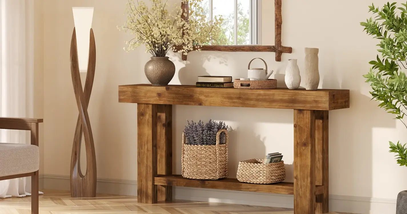
Tribesigns 55-inch entryway table Its clean lines and striking geometric base make a statement, adding a touch of refined charm to your space while effortlessly transforming everyday items into stylish displays.
The 1.96-inch thick tabletop is not only visually appealing but also highly functional. Crafted with engineered wood veneer, its smooth, durable surface is perfect for displaying sculptures, plants, or your favorite decorative pieces. At 55 inches in length, it offers ample space for arrangement. Additionally, its water-resistant coating ensures easy cleaning and maintenance, eliminating worries about spills or stains.

Specifications
|
Feature |
Detail |
|
SKU |
HOGA-JW0592 |
|
Product Dimensions (D x W x H) |
13.77"D x 55.11"W x 31.88"H |
|
Maximum Weight Recommendation |
200 Pounds |
|
Material Type |
Engineered Wood |
|
Color |
Grey |
|
Included Components |
Installation Tool |
Maintenance
Proper care will ensure the longevity and appearance of your console table.
- Cleaning: Wipe the surface with a damp cloth for general cleaning. For spills, wipe immediately with a dry cloth. Avoid harsh chemicals or abrasive cleaners.
- Dusting: Regularly dust with a soft, dry cloth.
- Avoid Direct Sunlight: Prolonged exposure to direct sunlight can cause fading or discoloration.
- Check Fasteners: Periodically check and retighten all screws and fasteners to ensure the table remains stable.
Related read: How to Maintain and Clean Wood Console Tables?
Tribesigns is committed to providing quality products and customer satisfaction. If you have any questions, require assistance with assembly, or need to report missing/damaged parts, please contact our customer service team.